Leave Your Message

How to Choose the Right Finned Tube Heat Exchanger?

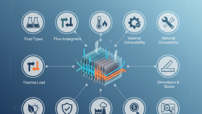
Choosing the right Finned Tube Heat Exchanger starts with the actual duty, not a catalogue image. What fluid must be heated or cooled? What temperatures, flow rates, and operating pressures apply? These details shape the required surface area, tube arrangement, fin spacing, and materials. A unit sized only for peak performance on paper may struggle when dust, moisture, or changing loads enter the picture.

The International Energy Agency’s Energy Efficiency 2023 report estimates that industry accounts for about 37% of global energy consumption. That figure is broad, not specific to finned-tube equipment, but it shows why practical heat-transfer decisions matter. A small pressure-drop penalty can affect fan or pump energy over many operating hours. Fouling can reduce output and increase cleaning needs. The U.S. Department of Energy’s process-heating guidance likewise stresses matching equipment to operating conditions and system requirements.

Heat-exchanger authority Sadik Kakaç’s published design guidance can be paraphrased in one useful principle: “Match the exchanger geometry to the thermal duty, while respecting pressure-drop and fouling limits.” Treat that as guidance, not a verbatim quotation. For a real selection, compare clean and fouled performance, allowable pressure drop, corrosion risk, maintenance access, and lifecycle cost. Look closely at fin spacing: tight fins may add surface area, but they can also trap debris. Measure the available footprint and check how technicians will reach the coil. Small details matter. Ask suppliers to document assumptions and performance data. Then review them against your plant’s measured conditions. No single design wins everywhere; even a careful estimate needs field validation.
How to Choose the Right Finned Tube Heat Exchanger?

Define Heat Duty with Q = ṁCpΔT and Specify Operating Temperatures

How to Choose the Right Finned Tube Heat Exchanger?

Define the heat duty before comparing fin density or tube materials. Use Q = ṁCpΔT for sensible heating or cooling. Here, ṁ is mass flow, Cp is specific heat, and ΔT is the fluid temperature change. Keep units consistent.

A practical example is 2 kg/s of air cooled from 80°C to 50°C. With Cp near 1.0 kJ/kg·K, the estimated duty is 60 kW. That number becomes the starting point for exchanger sizing.

Specify every important operating temperature. Record the hot-side inlet and outlet temperatures, cold-side inlet and outlet temperatures, and the surrounding air temperature. Include the minimum approach temperature. A small approach may improve heat recovery, but it usually requires more surface area. Check the maximum tube-wall temperature too. It can affect material strength, fouling, and fin attachment. Pressure drop also deserves attention, especially on the air side.

Field calculations are rarely perfect. Cp can change with temperature, and airflow may fluctuate during operation. A first estimate is still valuable. It exposes missing data early. I would recalculate the duty using expected minimum and maximum flow rates, not only the normal condition. Do not treat the 60 kW result as a final answer. Add realistic fouling allowances, verify temperature measurements, and ask whether the process can tolerate a warmer outlet. Small assumptions can quietly produce a large exchanger error.
Assess Air-Side Resistance: Typical Heat Transfer Coefficients Are 10–100 W/m²·K

How to Choose the Right Finned Tube Heat Exchanger?

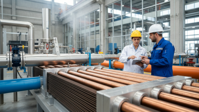
Air-side resistance often controls finned tube heat exchanger performance. Typical air-side heat transfer coefficients range from 10 to 100 W/m²·K, far below many liquid-side values. This difference matters. A design may have excellent tubes but still transfer insufficient heat through air. Check airflow rate, temperature, humidity, fin spacing, and surface cleanliness. Narrow fins increase area, yet they can collect dust and create a steep pressure drop.

In practical testing, I compare the calculated air-side coefficient with measured outlet temperatures and fan pressure. The result is rarely perfect. Real installations include uneven airflow, bypass leakage, and seasonal fouling. A clean laboratory value can therefore mislead. Use conservative assumptions when estimating resistance. Also examine the fan’s available pressure, because higher resistance usually means greater power demand and possible noise.

Tips: Start with the air-side pressure-drop limit, not only the required heat duty. Request performance data at the actual airflow and temperature range. Leave access for cleaning. A slightly wider fin pitch may reduce capacity, but it can improve reliability in dusty environments. Check both dry and wet conditions when condensation is possible. Do not trust one coefficient blindly. Test, compare, and revise.

How to Choose the Right Finned Tube Heat Exchanger?

Assess air-side resistance: typical air-side heat transfer coefficients are approximately 10–100 W/m²·K. Higher air velocity generally improves heat transfer but also increases fan power and pressure drop.

The ranges shown are representative engineering values for forced-air finned-tube heat exchangers. Actual performance depends on fin geometry, tube arrangement, air properties, fouling, and operating conditions.

Select Fin Geometry: Common Extended-Area Ratios Range from 5:1 to 25:1

A finned tube’s extended-area ratio compares its total outside surface with the bare tube’s outside surface; confirm the exact convention in the design specification. For many air-side applications, 5:1 to 25:1 is a useful screening range, not a universal target. At the lower end, wider fin passages can be easier to clean. At the upper end, added surface may improve heat transfer, but tighter passages can raise air-side pressure drop and collect dust. More area is not automatically better.

Kays and London’s Compact Heat Exchangers reports surface-area densities above 700 m²/m³ for compact exchanger designs. That figure describes area per exchanger volume, not finned-tube area ratio, so the two measures should not be confused. The ASHRAE Handbook—HVAC Systems and Equipment also supports evaluating exchanger performance alongside pressure drop and operating conditions. Check fin spacing against the actual air quality, moisture, and cleaning method. A dusty workshop may need more open spacing than a clean ventilation stream. I would not select 25:1 from a catalog number alone; fouling and fan limits can overturn the apparent gain. The right ratio depends on the whole system.

Choose Tube and Fin Materials for Temperature and Corrosion Conditions

How to Choose the Right Finned Tube Heat Exchanger?
Choose Tube and Fin Materials for Temperature and Corrosion Conditions

The tube material must suit the process fluid, pressure, and operating temperature; the fin must withstand the air-side environment. Carbon steel can suit many controlled, non-corrosive duties, while stainless steel or higher-alloy materials may be needed where moisture, chlorides, or aggressive chemicals are present. Aluminum fins transfer heat effectively in many applications, but wet, salty air can accelerate corrosion and damage tube-fin joints. Wet air changes everything. Check the full temperature range, including startup, shutdown, and cleaning—not just normal operation.

Corrosion is not a minor detail. NACE International’s IMPACT study estimated global corrosion costs at US$2.5 trillion, or 3.4% of global GDP, based on 2013 data. The report also noted that effective corrosion management could save 15–35% of those costs. These are economy-wide estimates, not exchanger-specific predictions, so use them as context rather than a sizing rule. Material compatibility charts help, but real condensate chemistry and deposits can differ from assumptions.

Tips: Write down fluid composition, chlorides, humidity, and minimum and maximum temperatures before requesting a quote. Confirm that dissimilar metals at fin-tube contact will not create a galvanic corrosion risk in the expected conditions. Ask for the proposed materials and corrosion assumptions in writing. Then inspect again. A material choice that looks safe on paper may still need review when site conditions change.

How to Choose the Right Finned Tube Heat Exchanger? - Choose Tube and Fin Materials for Temperature and Corrosion Conditions
Service Condition Recommended Tube Material Recommended Fin Material Typical Continuous Temperature Range* Corrosion Resistance Typical Applications Important Selection Considerations
Clean, dry air or mildly humid indoor air Copper Aluminum −40 to 150°C
(−40 to 302°F)
Good for general HVAC service Air-conditioning coils, comfort heating, ventilation units Provides high thermal conductivity and compact construction. Protect aluminum fins from salt, strong alkalis, and prolonged condensation.
Outdoor air with moderate humidity and occasional condensation Copper or stainless steel 304 Aluminum with protective coating −40 to 150°C
(−40 to 302°F)
Good with appropriate coating and drainage Outdoor air handlers, heat pumps, rooftop equipment Use corrosion-resistant coatings, adequate fin spacing, and drainage. Avoid water traps and direct contact between incompatible metals.
Coastal air, salt spray, or marine atmosphere Copper-nickel 90/10 or stainless steel 316L Coated aluminum or copper-nickel −40 to 200°C
(−40 to 392°F)
Very good, depending on exposure Marine HVAC systems, coastal process equipment, seawater-adjacent installations Uncoated aluminum is vulnerable to chloride attack. Use compatible tube-to-fin materials and verify coating performance under salt-spray conditions.
Freshwater or treated closed-loop water Copper, stainless steel 304L, or carbon steel Aluminum or galvanized steel Up to 200°C
(392°F)
Good when water chemistry is controlled Hydronic heating, closed-loop cooling, industrial heat recovery Check pH, chloride concentration, dissolved oxygen, and flow velocity. Carbon steel requires water treatment and external corrosion protection.
High-chloride water or brackish water Titanium or copper-nickel 90/10 Titanium, copper-nickel, or suitably coated aluminum Up to 200°C
(392°F)
Very good to excellent Desalination support systems, brackish-water cooling, marine process service Material selection must account for chloride level, temperature, velocity, and crevice conditions. Titanium offers strong resistance but has a higher material cost.
Dry flue gas or hot process air Carbon steel or stainless steel 304/316 Carbon steel or stainless steel 150 to 500°C
(302 to 932°F)
Good in dry service; depends on gas chemistry Waste-heat recovery, exhaust-air heating, furnace air preheating Use stainless steel when oxidation or contaminants are significant. Consider thermal expansion, fin attachment, fouling, and cleaning access.
Wet flue gas, acidic condensate, or sulfur-bearing gas Stainless steel 316L, duplex stainless steel, or nickel alloy where required Stainless steel or corrosion-resistant alloy 80 to 400°C
(176 to 752°F)
Good to excellent, subject to chemistry Condensing heat recovery, combustion-gas systems, chemical process exhaust Condensation can produce highly acidic liquids. Evaluate dew point, sulfur and chloride content, welds, crevices, and condensate drainage before finalizing materials.
High-temperature oil, thermal fluid, or clean process gas Carbon steel, stainless steel 304/316, or high-temperature alloy Carbon steel or stainless steel 200 to 600°C
(392 to 1112°F)
Depends mainly on fluid chemistry and temperature Thermal-oil systems, process heaters, high-temperature gas coolers Confirm allowable tube-wall temperature, oxidation resistance, thermal cycling, and pressure design. Aluminum fins are generally unsuitable at the upper end of this range.
Food, pharmaceutical, or hygienic process service Stainless steel 316L Stainless steel 316L or aluminum outside the hygienic boundary −40 to 300°C
(−40 to 572°F)
Very good with suitable surface finish Sanitary air systems, cleanroom equipment, product heating and cooling Specify cleanable geometry, smooth surfaces, compatible elastomers, drainability, and resistance to cleaning and sanitizing chemicals.
Strongly alkaline cleaning environment Stainless steel 316L or nickel-based alloy Stainless steel or compatible coated metal Up to 300°C
(572°F)
Good; aluminum is generally unsuitable CIP systems, chemical cleaning zones, industrial washdown areas Aluminum can be attacked by strong alkaline solutions. Confirm chemical concentration, temperature, exposure time, and galvanic compatibility.
Low-temperature refrigeration or cryogenic-adjacent air service Copper or stainless steel 304L Aluminum −196 to 80°C
(−321 to 176°F)
Good when moisture and refrigerant compatibility are controlled Refrigeration evaporators, low-temperature gas cooling, cold-storage equipment Check material toughness at low temperature, refrigerant compatibility, frost formation, defrost cycling, and fin spacing for airflow.

*Temperature ranges are typical material-selection guidance, not universal design limits. Final selection should be verified against pressure, thermal cycling, fluid chemistry, velocity, fouling, galvanic compatibility, welding requirements, and applicable engineering codes.

Verify Pressure Drop, Fouling Allowance, and Applicable TEMA/ASME Requirements

Choosing a finned tube heat exchanger starts with pressure-drop verification, not surface area. In practice, a compact exchanger can meet its duty and still fail the system budget. Check tube-side and air-side losses separately, including nozzles, headers, bends, and control valves. Many process designs reserve 10–20% pressure-drop margin, but this is not universal. Confirm the limit with the pump or fan curve.

Fouling allowance needs evidence from the actual service. TEMA Standards, 10th Edition, provide common fouling-resistance practices, while plant records offer better guidance. Hydrocarbon vapors, cooling water, and dusty air foul differently. A small resistance increase can reduce the clean heat-transfer coefficient sharply. Do not simply copy an old value. Consider cleaning intervals, fin spacing, fluid velocity, and corrosion products. Sometimes, more allowance creates an oversized and inefficient exchanger.

Mechanical compliance must be checked independently. ASME BPVC Section VIII, Division 1, 2023, addresses pressure-vessel design, materials, fabrication, and inspection requirements. TEMA covers exchanger construction details, vibration concerns, clearances, and testing practices. Match the selected class to design pressure, temperature, cyclic service, and inspection needs. A practical review should show design and operating cases side by side. Leave uncertainty visible. Field data is often incomplete. That weakness deserves a conservative, documented decision.